
Planning Dental Treatment Units: Space, Utilities, and Installation Needs


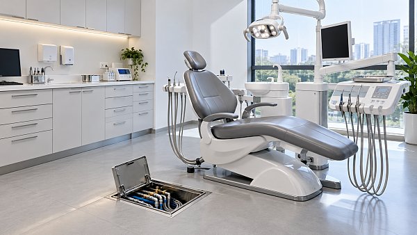
The dental chair fits the drawing, the contractor has installed the services, and delivery is booked. Then the installer finds that the suction connection is on the wrong side of the floor box—or that a service panel cannot open without removing cabinetry. Small coordination gaps can become expensive problems once finishes are complete.
Planning Dental Treatment Units therefore starts before installation day. Project managers and engineering leads need to connect the selected equipment configuration with room clearances, structural support, electrical supply, water quality, drainage, compressed air, and suction. The objective is not simply to make the unit operate at handover, but to make it accessible, maintainable, and compatible with the facility’s daily workflow.
Freeze the equipment configuration before freezing the room
A generic chair footprint is not a reliable construction reference. A treatment unit may combine a powered patient chair, delivery system, assistant’s instrumentation, operating light, cuspidor, monitor, foot control, and utility enclosure. Different mounting arrangements change both the working envelope and the position of service connections.
Before approving coordinated drawings, obtain the manufacturer’s installation package for the exact model, configuration, and destination market. A brochure may describe features; it rarely contains enough information to set out floor penetrations or size utility branches.
The equipment submittal should identify:
- Overall dimensions, full chair movement, and delivery-arm operating envelopes.
- Mounting details, equipment mass, anchorage requirements, and permitted floor conditions.
- Utility connection locations, sizes, elevations, and allowable connection zones.
- Electrical characteristics and any requirements for connected accessories.
- Water and air quality, pressure, and flow requirements.
- Suction-system compatibility, drainage arrangements, and service-access clearances.
Also verify the model’s intended use and applicable regulatory status in the installation market. Documentation for one regional version should not automatically be accepted for another. Changes to voltage, accessories, or supplied components can affect both installation and acceptance requirements.
Plan the working envelope, not just the chair footprint
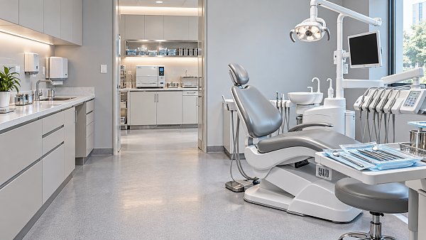
The meaningful space requirement is the area occupied during use. A reclined chair, an extended instrument arm, two stools, and an open cabinet drawer can consume substantially more room than the equipment outline suggests.
Review the layout with the clinical team using the actual delivery arrangement: over-the-patient, side delivery, rear delivery, or another manufacturer-supported configuration. Confirm whether the room must accommodate right- and left-handed operation. A layout that works well in one orientation may become awkward when the operator changes sides.
Map these movements on the same drawing:
- Patient entry, transfer, seating, and exit, including applicable accessibility provisions.
- Operator and assistant positions through the chair’s intended operating range.
- Delivery-arm, light-arm, monitor, and assistant-arm movement.
- Cabinet doors, drawers, room doors, and mobile equipment.
- Cleaning access and access to removable service covers.
A full-scale floor mock-up is often more useful than another round of dimension checking. Tape the equipment envelope onto the floor, place temporary stools and cabinet outlines, and test the workflow with users and installers. Include the reclined position and access needed for emergency response, not only the upright position shown in sales literature.

Do not adopt a universal minimum room size. Required dimensions depend on the equipment, workflow, accessibility rules, and local building requirements. The coordinated plan should show project-specific clearances rather than rely on an assumed “standard dental room.”
Build one utility schedule that every contractor uses
Separate plumbing, electrical, and equipment drawings can each be correct while still conflicting at the chair base. Create a single interface schedule linked to a common setting-out datum. Record connection coordinates, elevations, capacities, isolation points, and the party responsible for each interface.
Electrical supply: check the complete connected system
Confirm voltage, frequency, maximum input, and circuit requirements against the supplied model. Include lights, monitors, integrated instruments, and other accessories when establishing the electrical scope. The electrical designer should determine applicable protection, earthing, and any bonding requirements under local rules, including requirements for the room’s electrical classification.
Place isolation and connection points where authorized personnel can reach them without creating an obstruction. Coordinate power and data routes with moving chair parts, wet services, anchorage positions, and cleaning access. Where equipment connects to building networks, agree with IT on network configuration, security, and vendor support before commissioning.
Water: separate supply suitability from waterline management
Check whether the unit uses direct mains water, an independent bottle system, or a manufacturer-approved combination. Each arrangement has different implications for filling, isolation, backflow prevention, treatment, and maintenance.
Water that is acceptable for the building may still require conditioning for the equipment. Hardness, sediment, or unsuitable chemistry can affect valves and narrow tubing. Conversely, adding a filter or treatment device without checking compatibility may reduce available flow or introduce materials and chemicals the manufacturer does not permit.
Dental unit waterline management also needs an operating plan. Establish manufacturer-approved cleaning and disinfection procedures, applicable water-quality targets, monitoring arrangements, and responsibilities before handover. An independent bottle does not, by itself, resolve waterline biofilm risk. Where sterile irrigant is required for an intended procedure, confirm a suitable sterile delivery pathway rather than assuming routine unit waterlines provide one.
Compressed air and suction: assess performance under load
For compressed air, verify the required quality, dryness, pressure, and flow at the treatment unit—not only at the compressor outlet. Pipe length, fittings, restrictions, and simultaneous demand can cause pressure losses. Size the system for the planned operating pattern and a defined expansion allowance, rather than an unspecified future capacity.
Suction requires a coordinated design. Confirm whether the treatment unit is intended for a wet or dry arrangement, where separation occurs, and what the manufacturer specifies for pipework and operating performance. Use appropriate routing and provide access for maintenance. Check applicable wastewater and amalgam-separation requirements where relevant to the facility’s activities.
Locate compressors and suction plant with attention to ventilation, heat rejection, noise, vibration, drainage where needed, and maintenance access. Moving plant away from treatment rooms can improve the room environment, but longer service runs must still satisfy equipment performance requirements.
Resolve floor, drainage, and service access before finishes
Floor-mounted Dental Treatment Units need a verified support and anchorage arrangement. The installer should know the substrate type, thickness where relevant, and any restrictions before drilling. Do not assume that a finished floor provides adequate anchorage, or that a raised floor can support the unit without a designed solution.
Check existing slabs for concealed services, reinforcement constraints, and post-tensioning where applicable. Coordinate penetrations with structural and fire-safety requirements. In refurbishment projects, early surveys are especially valuable because record drawings may not reflect previous alterations.
Drainage deserves its own review. Not every configuration has the same discharge requirements; a unit without a cuspidor may differ from one with an integrated bowl and water system. Confirm which connections are actually required, then check gradients, venting, traps, and access under the applicable plumbing design.
Service accessibility should be demonstrated, not merely noted. Ask the supplier to identify which covers open, which components may need replacement, and how much working space technicians require. A concealed utility box can look tidy while making a routine repair unnecessarily disruptive.
Sequence installation around evidence-based hold points
A practical installation programme separates room readiness from equipment readiness. Agree hold points with the supplier and contractors so that unresolved infrastructure work is not discovered after the unit is unpacked.
- Before rough-in: approve coordinated equipment drawings, utility schedules, anchorage details, and responsibilities.
- Before closing floors or walls: inspect connection locations, test concealed services as specified, and retain photographs with dimensions.
- Before delivery: confirm access routes, unloading arrangements, room condition, floor readiness, and available utilities.
- Before connection: flush, clean, and test service lines using agreed procedures; verify supply conditions against manufacturer limits.
- Before acceptance: complete functional checks, documentation review, and staff instruction.
Protect new equipment from construction dust, moisture, and impact. If installation must overlap with other trades, define protection measures and responsibility for damage. Whenever possible, complete disruptive overhead and finishing work before sensitive equipment enters the room.
Commission the operatory as a system
A chair that moves and a light that switches on do not demonstrate installation readiness. Commissioning should follow manufacturer procedures and applicable local requirements, with recorded acceptance criteria agreed in advance.
Verify chair travel, controls, safety features, instrument functions, light positioning, and any supplied accessories. Check connections for leaks, confirm isolation points, and record relevant electrical safety checks. Measure utility performance at the unit under representative demand; in a multi-chair facility, include an agreed simultaneous-use test.
Inspect the room during operation. Does a hose snag at full recline? Can the assistant reposition equipment without striking cabinetry? Is suction noise intrusive? These observations can reveal coordination defects that individual component tests miss.
Waterline preparation and verification should follow the manufacturer’s instructions and applicable local guidance. Networked accessories need their own connection and workflow checks where included in the project scope. Record defects with an owner, correction date, and retest requirement rather than accepting verbal assurances.
Make handover useful for the maintenance team
The handover package should include model and serial numbers, as-built service locations, installation and operating instructions, test records, warranty conditions, and supplier contacts. Add maintenance schedules, approved consumables, waterline procedures, and any required inspection or calibration arrangements for supplied components.
Identify who maintains shared plant, who monitors water quality, and who responds when several rooms lose suction or air. Training should cover routine operation, approved cleaning, shutdown, basic fault reporting, and the limits of user servicing.
The most reliable planning decision is to treat every interface as a deliverable. When room layouts, utility performance, installation responsibilities, and acceptance evidence are settled together, Dental Treatment Units become easier to install—and far less troublesome to support after the project team leaves.
Want to dive deeper into these market dynamics, or need data-driven support for your next business move? Drop a line below and let the analysts at GMLE provide customized insights.
We respect your privacy. Your information is strictly confidential.
Recommended for You
 Technology & Performance BenchmarkMedical Imaging Equipment Explained: What X-Ray, CT, MRI, and Ultrasound ShowMedical Imaging Equipment explained: discover what X-ray, CT, MRI, and ultrasound show, and compare workflow, safety, and lifecycle costs to make smarter purchasing decisions.By:Oct 22, 2026
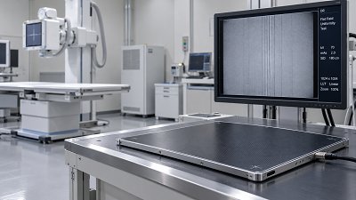
 X-Ray & CTRecurring Artifacts in Digital X-Ray Machines: Detector or Calibration?X-Ray Machines showing recurring lines, bands, or ghosting? Learn how to distinguish detector faults from calibration issues, avoid unnecessary replacement, and verify image quality.By:Oct 22, 2026
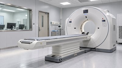
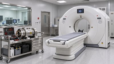
 Market Pricing & CostCT Scanner Ownership Costs: Service, Tube Replacement, and UtilizationCT Scanners cost more than the purchase price. Explore service contracts, tube replacement, and utilization to compare lifecycle costs and make a smarter investment.By:Oct 22, 2026
 MRI & Imaging Software1.5T vs. 3T MRI Systems: Which Fits Your Clinical Case Mix?Compare 1.5T and 3T MRI Systems to find the right fit for your clinical case mix. Explore image quality, implant conditions, workflow, and costs to make a smarter investment.By:Oct 22, 2026
 Technology & Performance BenchmarkLaboratory Centrifuges: Why RCF Matters More Than RPM in Sample ProtocolsLaboratory Centrifuges: Learn why RCF matters more than RPM, avoid rotor conversion errors, and discover key checks for consistent sample separation and safer protocol transfers.By:Oct 22, 2026
 Validation & TraceabilityAutoclave Validation: What Biological and Chemical Indicators Can ProveAutoclaves need more than passing indicators. Learn what biological and chemical tests prove, avoid release errors, and strengthen your validation process.By:Oct 22, 2026
 Portable UltrasoundPortable Ultrasound Machines for Bedside Care: Choosing Probes and FeaturesCompare portable Ultrasound Machines for bedside care. Explore probe options, image quality, battery life, and connectivity to choose a system that fits your clinical workflow.By:Oct 22, 2026
 Supply Chain & ProcurementDental Equipment for a New Clinic: What to Buy First and What Can WaitDental Equipment for a new clinic: discover what to buy first, what can wait, and how to compare suppliers. Plan a safe opening, control costs, and invest confidently as demand grows.By:Oct 22, 2026
 Dental Treatment UnitsPlanning Dental Treatment Units: Space, Utilities, and Installation NeedsPlanning Dental Treatment Units? Discover essential space, utility, and installation requirements to avoid costly rework, streamline setup, and keep your dental practice running smoothly.By:Oct 22, 2026
 Automated ChemistryChoosing Biochemistry Analyzers: Match Throughput and Test Menus to Lab DemandChoosing Biochemistry Analyzers? Learn how to match throughput, test menus, and operating costs to lab demand—and compare systems confidently beyond headline specifications.By:Oct 22, 2026


Device Topic
Equipment Selection Guide
Reference Article • Technical Topic • Life Cycle Cost
Newsletter Digest
Browse equipment comparisons and practical reading on imaging, laboratory systems and procurement. Newsletter delivery is not connected.
Leave A Message
If you are interested in our products and want to know more details, please leave a message here, we will reply you as soon as we can.